
Images are representations only.
Description
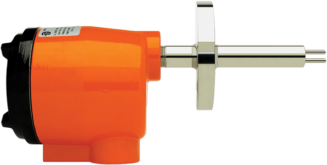
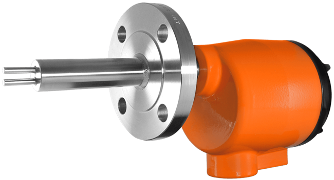
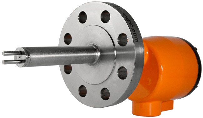
The Kayden CLASSIC 812 Flow, Level, Interface Switch & Transmitter features a precision-welded, highly accurate stainless steel sensor.
Ideal for liquids, gases, and slurries in a clean or dirty process, the CLASSIC 812 is available in a wide range of flange sizes and insertion lengths. Kayden's electronic thermal dispersion flow and level switches have no moving parts to foul, clog, or stick, resulting in exceptional reliability and requiring little to no maintenance.
The CLASSIC 812 is available with a Raised Face or RTJ flange in a wide range of flange sizes, ANSI ratings, and customer-specified insertion lengths. All Kayden models feature a rugged flameproof enclosure with blind or lens covers available.
- Process Connection
- Raised Face or RTJ Flange
- Adjustable Set Point Range
- 0-254 feet/s
- 0-77 meters/s
- Insertion 'U' Length
- inch 2.5" to 120" in 1/2" increments
- cm 6.4 to 305 in 1 cm increments
- Input Power
- 12-24 Vdc & 115-230 Vac, 50-60 Hz
- Operating Pressure - Maximum
- Per Flange Rating, ASME B16.5
- Temperature Range - Sensor
- -55° to 200° C
- -67° to 392° F
- Local Enclosure
- Aluminum Flameproof
- 1" Female NPT Conduit Connection
- Local Enclosure Cover
- Blind or Glass Lens, Flameproof
- Wetted Materials
- 316/316L Stainless Steel
- Other Materials Available
- Outputs/Communications
- Two Independent Relays - SPDT
- 4-20 mA
- Modbus
- Rated 120 Vac max, 30 Vdc max, 4 A max
- Approvals
- CSA
- CRN
- Single Seal
- NACE
- NEMA 4, 4X, 6P, IP65/67
Inventory
Displaying price & availability for United States in USD Change Location or currency.
1 model matching criteria
KAYDEN CLASSIC Thermal Flow,Level,Interface Switch, Modbus, 2" 300# RF SST, 5"U, Lens, CSA/CRN
show more
- Process Connection
- 316 Stainless Steel Flanged
- Raised Face 2"
- ANSI: 300
- Adjustable Set Point Range: 0-254 feet/s, 0-77 meters/s
- Insertion 'U' Length: 5"
- Input Power: 12-24 VDC & 115-230 VAC, 50-60 Hz
- Operating Pressure (Maximum): Per Flange Rating, ASME B16.5
- Temperature Range (Sensor): -45°C to 200°C, -50°F to 392°F
- Local Enclosure: Aluminum Flameproof, 1" FNPT
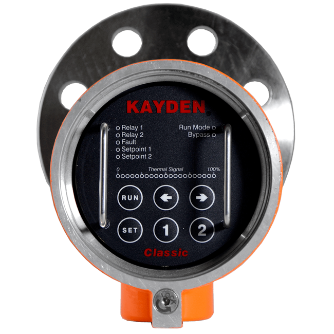
- Cover: Flameproof Glass Lens Cover
- Remote Electronics Enclosure and Cover: Not Required
- Wetted Materials
- 316 Stainless Steel
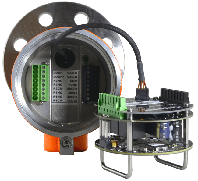
- Outputs/Communications
- Two Independent Relays (SPDT)
- 4-20 mA (Thermal Signal, Scalable)
- Modbus Communication via RS-485
- RCMS (Remote Control & Monitoring Software)
- Electronics - Standard Features
- Automated Redundant Self-Test Diagnostics
- Display Panel Lock-Out
- Easy Set-up
- No Mechanical Jumpers or Trim Pots
- Intelligent Push Button Interface
- Constant Display of Operation (Flow/Level)
- Start-Up Bypass Timer
- Approvals: c CSA us (UL Standards), CRN (Canada-wide), Single Seal, NACE, NEMA 4 [/li]
In Stock
1 - 2 weeks
Non-Cancellable / Non-Refundable
$2,426.36USD
Configure
Specifications
Specifications
Brand
Insertion 'U' Length
- Custom 'U' Lengths 2.5” to 120” (6.4 cm to 305 cm) Available in 1/2” (1.0 cm) Increments.
Flange Size - 1” (DN 25)
- 1” (DN 25) - 150#
- 1” (DN 25) - 300#
- 1” (DN 25) - 600#
Flange Size - 1-1/2” (DN 40)
- 1-1/2” (DN 40) - 150#
- 1-1/2” (DN 40) - 300#
- 1-1/2” (DN 40) - 600#
Flange Size - 2” (DN 50)
- 2” (DN 50) - 150#
- 2” (DN 50) - 300#
- 2” (DN 50) - 600#
Flange Size - 3” (DN 80)
- 3” (DN 80) - 150#
- 3” (DN 80) - 300#
- 3” (DN 80) - 600#
Flange Size - 4” (DN 100)
- 4” (DN 100) - 150#
- 4” (DN 100) - 300#
- 4” (DN 100) - 600#
Flange Size - 5” (DN 125)
- 5” (DN 125) - 150#
- 5” (DN 125) - 300#
- 5” (DN 125) - 600#
Flange Size - 6” (DN 150)
- 6” (DN 150) - 150#
- 6” (DN 150) - 300#
- 6” (DN 150) - 600#
Flange Size - 8” (DN 200)
- 8” (DN 200) - 150#
- 8” (DN 200) - 300#
- 8” (DN 200) - 600#
Flange Size - 10” (DN 250)
- 10” (DN 250) - 150#
- 10” (DN 250) - 300#
- 10” (DN 250) - 600#
Storage Temperature
- Product Should be Stored in a Clean & Dry Environment between -30° & 60° C (-22° & 140° F)
Switch Type
- 2 SPDT Sealed Relay Contacts Rated @ 4 Amps Resistive 230 Vac or 30 Vdc, Max.
Cover - for Local Enclosure
- Blind Cover - Flameproof
- Glass Lens Cover - Flameproof
Remote Electronics Enclosure & Cover
- Glass Lens Cover - Flameproof
Wetted Materials
- 316, 316L Stainless Steel
- All-Welded Construction
- Hastelloy C-276
- Other Metals Available
- Titanium Grade 2
Remote Control & Monitoring Software
- Adjust Relay Modes
- Adjust Set Points 1 & 2
- Load or Save User Settings
- Lock or Unlock the Display Panel to Protect the Settings
- Many Other Adjustable Features
- Modify Heater Settings to Optimize Response Time
- Monitor Operating Status
- Operated Via a Personal Computer Locally or from a Remote Control Center
- Visualize the Actions of the Process Via the Graphical Display
Environmental Protection
- IP55
- NEMA 4 / IP55
Principle of Operation
- Thermal, Calorimetric
Input Power
- 12-24 Vdc, 120-240 Vac, 50/60 Hz
- Power Consumption: Max.
- Universal Power Input
Enclosure, Body Material
- Copper-Free Aluminum (Does Not Exceed 0.4 % Copper)
Enclosure Finish
- Powder-Coated Polyester TGIC
Electronics - Standard Features
- *Configurable only from the Kayden RCM Software
- 100 % Digital Design. Electronics are Environmentally Sealed
- 4-Adjustable Independent Switch Point Timers
- Automated Redundant Self-Test Diagnostics
- Display Panel Lock-Out*
- Easy Setup: No Mechanical Jumpers or Trim Pots
- Incrementally Adjustable Heater Power (5 % Steps) with Automatic Over-Range Protection
- Intelligent User Interface with Push-Button & Constant Display of Operation (Flow/Level)
- Start-Up Bypass Timer
- Temperature Compensation
- Temperature Mode*: Process Temperature may be Displayed/Graphed in Flow/Level Mode
Applications
- Flow
- Interface
- Level
Communication
- Modbus RTU Communication-Alarms, Flow Status & Diagnostics
- RS-485 Using Kayden's Remote Control & Monitoring Software (RCMS) or other Modbus Compatible Software
Response Time
- Approximately 0.5 to 30 seconds
Output
- 4-20 mA (Thermal Signal, Scaleable) Rates 120 Vac, Max.
Flange Type
- Raised Face (RF)
- RTJ - Ring Typical Joint
Flange Material
- 316, 316L Stainless Steel
- Other Exotic Metals Available
Enclosure, Body Details
- 1” NPT Female Conduit Connection
- Buna-N O-Ring on Cover
Accuracy
- Flow Service: ± 1.0 % of Set Point Velocity over Operating Range of ± 28° C (± 50° F)
- Level Service: ± 0.64 cm (0.25”)
Operating Temperature - Electronics
- -55° to 65° C (-67° to 149° F)
Sensor, Probe Style
- Insertion
Switch Point Range
- Gases: 0.25 to 200 sfps, 0.08 to 60 SMPS - Standard Condition 21° C (70° F) at 14.7 psi (1 Atm)
- Hydrocarbon-based Liquids: 0.01 to 5.0 FPS, 0.003 to 1.50 MPS
- Water-based Liquids: 0.01 to 3.00 FPS, 0.003 to 0.9 MPS
Operating Temperature - Sensor
- -55° to 200° C, (-67° to 392° F)
Approvals & Certifications
- CRN
- CRN - Canadian Registration Numbers - 1” & 1-1/2” - Flanges Approved for All Provinces & Territories 812-RAA Series: CRN # 0F13787.2C 316, 316L Stainless Steel, Pipe NPS 1/2” Schedule 80 Code of Construction: ASME B31.3, Max.
- CRN - Canadian Registration Numbers - 2” through 10” Flanges - Approved for All Provinces & Territories 812-RAA Series: CRN # 0F13773.2C 316, 316L Stainless Steel, Pipe NPS 3/4” Schedule 80 Code of Construction: ASME B31.3, Max.
- CSA
- CSA - Local (Sensor) Enclosure Flameproof: Class I, Div. 1, Groups B, C, D, Ex d IIB + H₂ AEx d IIB + H₂ (Class I, Zone 1, Group IIB + H₂) Temperature Code: T3 Enclosure Typical 4, IP55 Single Seal Approved Per ANSI/ISA 12.27.01-2003
- CSA - Remote Electronics Enclosure - Optional Flameproof: Class I, Groups B, C, D, Ex d IIB + H₂ AEx d IIB + H₂ (Class I, Zone 1, Groups IIB + H₂) Temperature Code: T3
Operating Pressure - Sensor
- Maximum
Applications
Applications
Flow
- Ammonia Storage
- Biogas Flow
- Catalysis Vessels
- Chemical Injection & Additive Flow Monitoring
- Chemical Reactors
- Chlor-alkali Processes
- Compressors
- Condensers
- Deionization Tanks
- Digester Gas Flow
- Distillation Columns
- Drain Line Flow
- Emergency Eye Wash & Shower Stations
- Fermentation Vessels
- Flare Gas Monitoring
- Flare Knock-out Drums
- Flow Monitoring & Verification
- Heat Exchangers
- Heat Recovery Steam Generator (HRSG) - Power & Utilities
- High Pressure Flows
- Leak Detection
- Lube Oil Systems
- Monitoring Purge Air Flow
- Natural Gas to Boilers
- Pumps
- Reboilers
- Refinery Flow Applications
- Relief Valve & Rupture Disk Flow Monitoring
- Remote Indication of Flow via Analog Output & Digital Communications
- Pump Protection - Dry Alarm
- Tank Blanketing
- Tank Overflow Protection
- Tanker Loading & Unloading
- Water & Wastewater
- Vaporizers
- Vent Monitoring
Level
- Biogas Dehydration
- Blending Operations
- Carbon Slurry Level
- Compressor Scrubber
- Compressor Waste Liquid
- Condensate Receiver Tanks
- Cooling Tower Basins
- Crude Desalting
- Crude Dehydration
- Deionization Tanks
- Digester Blow Tanks
- Free Water Knock-out Tanks - High, Low and Interface Level
- Geothermal - Degasser Tanks
- Geothermal - Steam & Brine Separators
- Leak Detection (Accumulation Reservoir)
- Lime Slurry Level
- Mixing & Blending Systems
- Oil Separators & Treaters - High, Low & Interface Level
- Production Fluid Storage
- Pulp Bleaching Towers
- Pulp Digesters
- Pulp Storage
- Pulp Washing Systems
- Sampler Systems
- Sand Separators
- Scrubber Vessels
- Storage Tanks
- Sumps - All Types of fluids: Water, Oil, etc.
- Surge Tanks
- Tank Overflow
- Turpentine Recovery
- Vapor & Liquid Separation
- Vapor Recovery
Interface
- Crude Desalting
- Interface Control in Separation Vessels
- Interface Detection
- Interface Control & Level Detection in Settling Vessels
- Liquid-Liquid Extraction - LLX
Media
- Liquids, Air & Gases
- Slurries
- Corrosive Liquids
Areas
- Flameproof, Hazardous & General-Purpose Areas
IDEAL PROCESS CONDITIONS FOR FLOW
Liquids
- Consistent Process Composition & Temperature
- Sufficient Straight Run Flow Profile (minimizes turbulence)
- Recommended Minimum of 5 Pipe Diameters from any Disturbance
Air & Gas
- Consistent Process Composition & Temperature
- Sufficient Straight Run Flow Profile (minimizes turbulence)
- Clean and Dry
Slurries
- Consistent Process Composition & Temperature
- Sufficient Straight Run Flow Profile (minimizes turbulence)
Emulsion
- Consistent Process Composition & Temperature
- Sufficient Straight Run Flow Profile (minimizes turbulence)
UNDESIRABLE PROCESS CONDITIONS FOR FLOW
Liquids
- Inconsistent Process Composition or Temperature
- Insufficient Straight Run
- Aerated Fluids
- Turbulence
Air & Gas
- Inconsistent Process Composition or Temperature
- Wet or Saturated Air & Gas
Slurries
- Inconsistent Process Composition or Temperature
- Insufficient Straight Run
- Aerated Fluids
- Turbulence
Emulsion
- Inconsistent Process Composition & Temperature
- Insufficient Straight Run
- Aerated Fluids
- Turbulence
Solids
- Dry granulated processes are NOT good candidates for thermal switches
Documentation
Documentation
Data Sheets
Product Manuals
- Product Manual - Kayden Classic 800 Flow to Velocity Quick Reference Guide pdf 6.2 MB
- Product Manual - Kayden CLASSIC 800, Nov 2022 pdf 17.6 MB
- Product Manual - Kayden Modbus Protocol Register Declarations for 800 Series pdf 116 KB
- Product Manual 0 Kayden Classic 800 quick setup guide v5.2.pdf 2.6 MB
Application Considerations
Application Notes
- Application Note - Kayden 4-20mA Analog Output pdf 766 KB
- Application Note - Kayden Acid Level Detection pdf 1.4 MB
- Application Note - Kayden Fail Safe pdf 894 KB
- Application Note - Kayden High Level Detection Holding Tank pdf 996 KB
- Application Note - Kayden Leak Detection pdf 1.5 MB
- Application Note - Kayden Monitoring Digester Flow pdf 831 KB
- Application Note - Kayden Oil Water Separation pdf 1.2 MB
- Application Note - Kayden Pulp and Paper Digester Tank pdf 1.1 MB
- Application Note - Kayden Pulp and Paper Skimmer Tank pdf 829 KB
- Application Note - Kayden Pump Monitoring and Protection pdf 1.0 MB
- Application Note - Kayden Pump Monitoring and Protection Remote pdf 1.2 MB
Catalogs
Certifications & Approvals
Outline Drawings
- 2021 Outline Dimension Drawing - Kayden CLASSIC 812 Local Enclosure Raised Face pdf 284 KB
- 2021 Outline Dimension Drawing - Kayden CLASSIC 812 Remote Enclosure Raised Face pdf 770 KB
- Legacy Outline Dimension Drawing - Kayden CLASSIC 812 Local Enclosure Raised Face pdf 296 KB
- Legacy Outline Dimension Drawing - Kayden CLASSIC 812 Remote Enclosure Raised Face pdf 701 KB